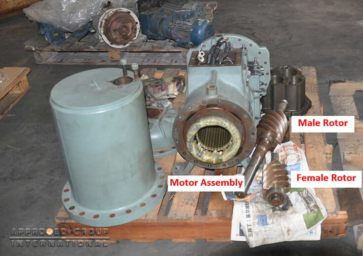
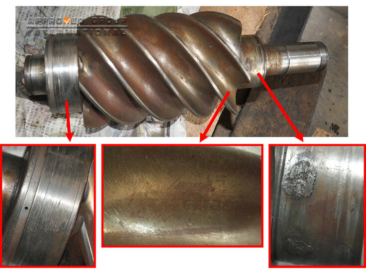
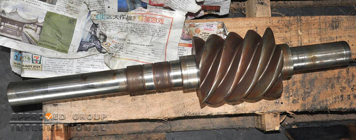
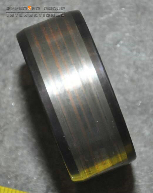
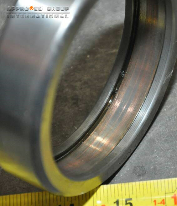
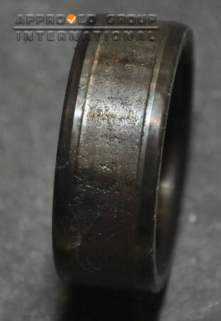
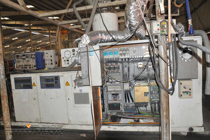
A chiller and an extruder were reported to have failed in a plastic pipe and container manufacturing company. The incident was discovered by the supervisor during heavy rain and thunderstorm. He noticed that the chiller stopped operating while the circuit breaker for one (1) of the seven (7) operating extruders had tripped. Upon inspection, the screw compressor for the chiller and the two (2) power converter units for the extruder were reported to have been damaged. The Hitachi water-cooled chiller was used to cool the extruders in the production area. It comprises of two (2) screw compressors, an evaporator, a water-cooled condenser and an expansion system. The allegedly damaged component of the chiller was the semi-hermetic horizontal screw compressor that allows high compression ratios to be achieved. The compressor was driven by an electric motor consisting of a pair of screw rotors: a male and female rotor, set in a stationary housing with the suction and discharge ports. Two (2) power converter units, each consisted of a controller board, a field supply board and a “Dual DAC 12” daughterboard of the extruder were allegedly damaged. The female rotor in Figure 1 was partially corroded and sustained uniform wear on the interlobe surface. The inner rotor shaft on the discharge side was found to be damaged, where weld marks and loss of material was observed on the surface. The bearing support on the suction side was also damaged, where scratch marks were observed (Figure 2). The male rotor was found to be in relatively good condition. Normal wear marks were observed on the lobe surface and there was no additional damage on the rotor and shaft. (Figure 3) The wear marks on the lobe surface of the male rotor were found to be consistent with the wear marks on interlobe surface of the female rotor, resulting from the compression process. The motor winding was damaged.
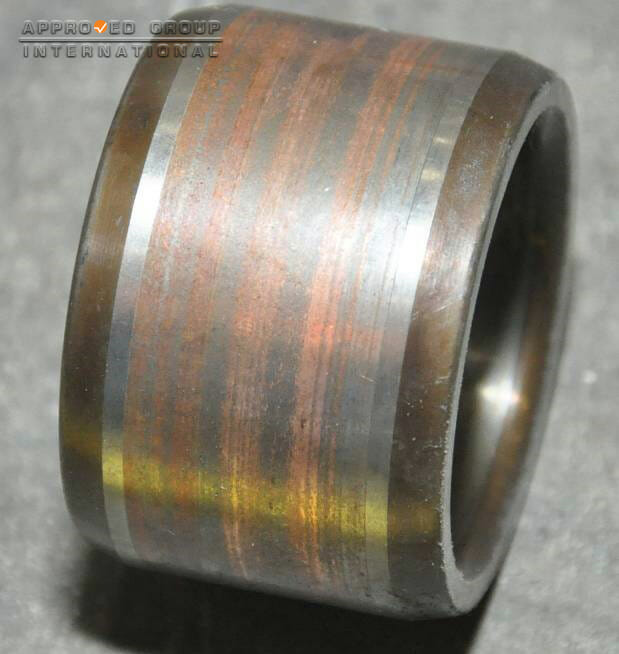
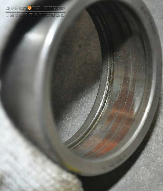
Bearing 1
Bearing 2
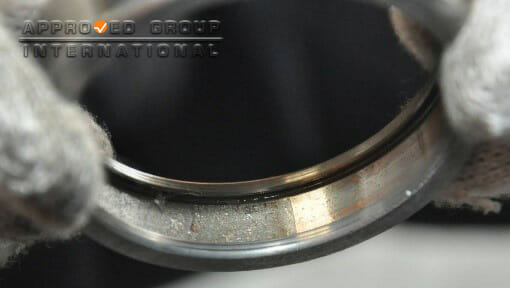
Bearing 3
Figure 4: Bearings
The finding of flaking or spalling on the inner and outer rings of the bearing provides a strong indication of fatigue failure on the bearing. The failed bearing would have caused the screw compressor to operate under high load or working conditions.
This can be indicated by the abnormal and non-parallel path patterns of the other 2 bearings. More current would be required for the motor to operate under such high load condition and this eventually resulted in short circuiting of the motor’s windings and tripping of the circuit breaker for the chiller.
Based on the investigation and examination, the failure of the screw compressor for the chiller was originated from fatigue failure of 1 of the bearings.
The extruder was able to be switched on. However, the motor could not operate. Error messages were also displayed by the two (2) power converter units. The ‘H21’ Light Emitting Diode (LED) for the left and right power converter units was lit.
This indicates a controller inhibit that caused an operational disturbance to the extruder. The Controller Board for the right power converter unit also displayed an error message ’01’, which indicated a disturbance or missing voltage of ±24 volts, as an effect of the controller inhibit.
A controller inhibit would result in the de-energising of the power converter and the dropping of the main contactor. This caused the main drive motor to stop operating without braking.
Voltage measurements using a multimeter on the terminal strip of the Processor Board of both power converter units revealed that 24 volts was supplied to the board, indicating that the two (2) power converter units could still be energised and thus there was no damage to the power supply.
An insulation test was also conducted on the two (2) main drive motors and there was no fault detected on the motors, which indicates that the motors were not damaged.
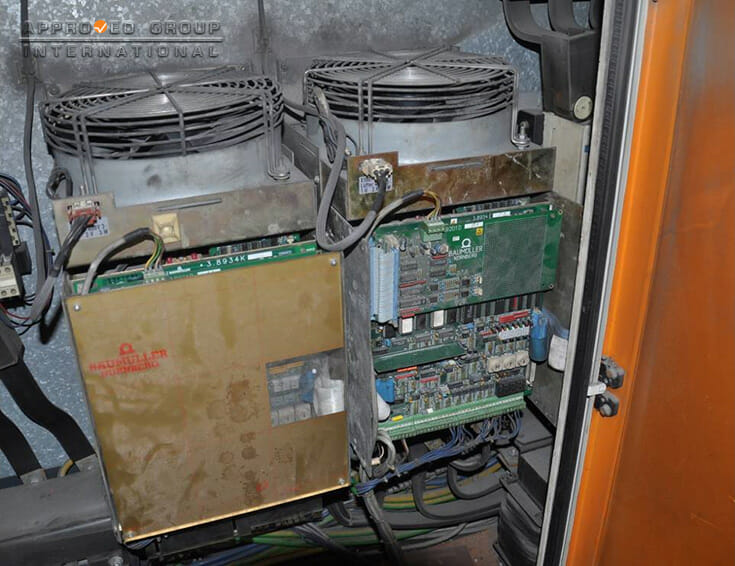
Based on the investigation and examination, the failure of extruder originated from an internal component fault of the two (2) power converter units within the electrical cabinet.