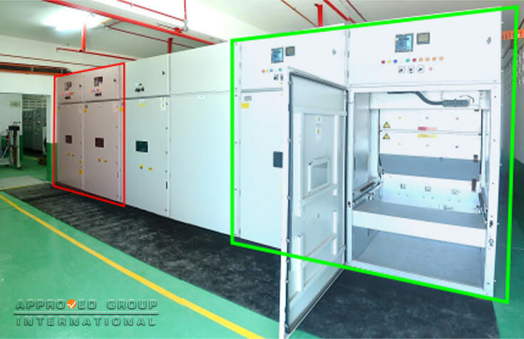
At approximately 0100 hours on Thursday, 7 September 2017, a flashover was reported to have occurred when the premises encountered a power disruption that caused the entire production line to shut down. The management then informed Tenaga Nasional Berhad (TNB, the utility company) to identify the cause of the power disruption. The TNB narrowed the cause of the power disruption to the failure of the thirty-three kilovolts (33 kV) switchgear equipment. The contractor of the switchgear equipment found that the 33 kV Outgoing Vacuum Circuit Breaker (VCB) displayed burn marks at the cable terminations of Line 2. The exterior of the switchgear panel did not show any deformation or damage, except for some soot deposits observed on the gaps of the panel cover at the rear compartment of the cubicle for the Outgoing VCB for Line 2. The interior surfaces at the front compartment of the cubicle for the Outgoing VCB for Line 2 also did not display any indication of damage. However, upon opening the lower rear panel cover of the cubicle for the Outgoing VCB for Line 2, soot deposits were observed on the interior surface of the panel cover, albeit being partially cleaned.
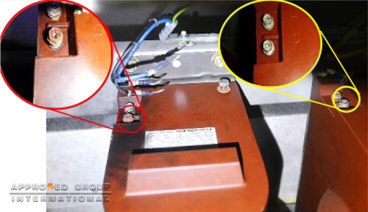
Several bolts and washers at the mounting points of the isolation contact spout bushing were partially oxidised (Figure 2). The insulation sheath around the cable terminals for the blue- and red-phases displayed slight charring and heat damage. However, the cable lugs were physically intact.
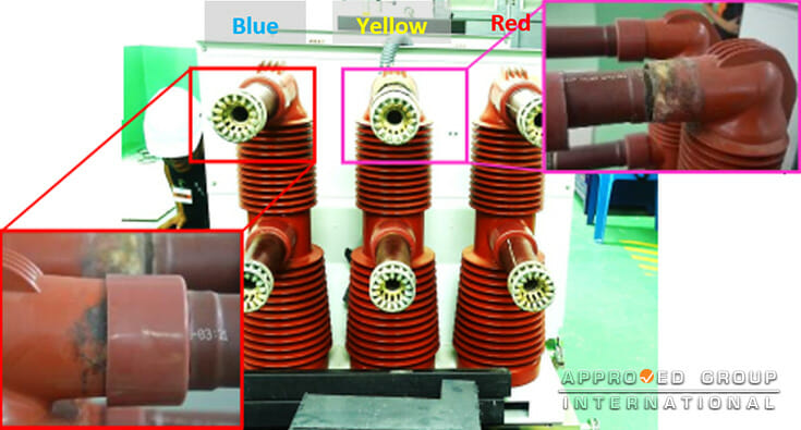
A close examination of the un-racked Outgoing VCB revealed that the upper insulated poles for the yellow- and blue-phases sustained burn marks (Figure 3).
The upper insulated pole for the yellow-phase displayed the most severe damage as the pole insulated sleeve had detached, with severe burn marks observed on the edges of the sleeve.
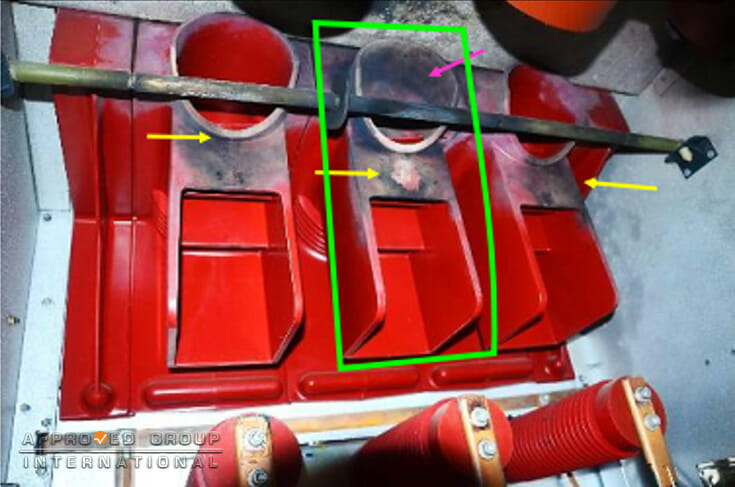
The examination on the moving (Figure 4) and fixed isolation contact spout bushings within the lower rear compartment of the cubicle revealed that the damage was most severe on the yellow-phase bushing, which is consistent with the severe damage sustained by the upper insulated pole on the Outgoing VCB. Based on the site inspection, the AFSB Team found that the flashover had affected the Outgoing VCB for Line 2 while the Incoming VCB for the same line was still in good physical condition. Thus, based on the examination, the Team found that the area of origin of the flashover was found to be at the yellow-phase of the Outgoing VCB of Line 2.
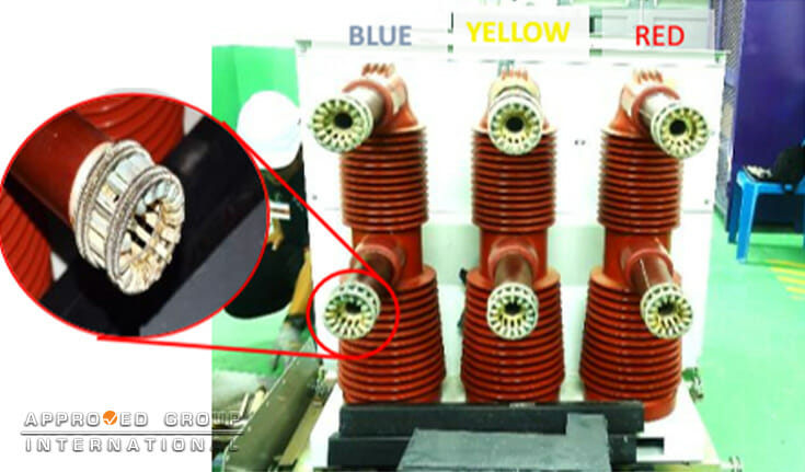
The presence of contaminants such as dust, liquid or salt on the non-conductive materials can induce the event of arc flash or flashover. Electrical currents can flow through water or moisture only when the water or moisture contains contaminants such as dirt, dust or mineral deposits. Based on the Team’s investigation, the Team noted that there were signs of oxidation observed on the surfaces of the tulip contacts (Figure 5). Several bolts and washers on the mounting points of the isolation contact spout bushing were also observed to be oxidized.
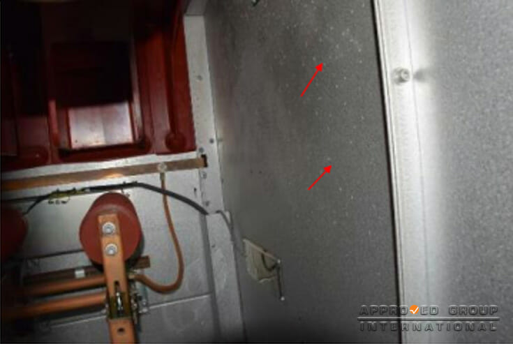
Whitish, powdery spots indicating condensation water marks were observed on the interior surfaces of the panel covers (Figure 6). The condensation process within the switchgear panel is likely due to the high air humidity that caused the warm air within the switchgear panel to condensate on cooler surfaces, such as the cover panel surface, bolts and washers. With the presence of moisture and minute dust particles, a conductive path would allow current to flow through the gaps on the insulated pole sleeves and subsequently cause a flashover, resulting in burn marks as seen on the insulated pole.
Therefore, the flashover occurred due to moisture build-up along the gaps of the insulation material on the insulated pole sleeves of the Outgoing VCB of Line 2.